Understanding EMI Shielding in Aviation Cable: Critical Protection for Flight Systems
What are the EMI Shielding Properties of Aviation Cable?
In the demanding world of aviation, where complex electronic systems operate side-by-side, ensuring reliable communication and control is paramount. Electromagnetic Interference (EMI) poses a significant threat to signal integrity and system performance. This is where the EMI shielding properties of aviation cable become a non-negotiable line of defense, making them fundamentally different from standard cables. Understanding these properties is crucial for engineers, designers, and maintainers working on aircraft systems.
Why EMI Shielding is Mission-Critical in Aviation
Aviation environments are rife with potential EMI sources:
- High-Power Systems: Radar transmitters, avionics computers, navigation equipment, engine ignition systems, and communication radios.
- Variable Frequency Drives (VFDs): Used in modern aircraft for controlling systems like cabin air compressors.
- Digital Data Busses: High-speed networks (like ARINC 429, Mil-STD-1553, AFDX) carrying critical flight data.
- Switching Power Supplies: Found in virtually all electronic equipment onboard.
Without effective shielding:
- Crosstalk: Signals from one cable could induce unwanted noise in adjacent cables (e.g., navigation signals disrupted by communication traffic).
- Signal Degradation: Critical data (engine parameters, flight control commands) could become corrupted, leading to faulty instrument readings or lost data.
- System Malfunctions: Severe EMI can cause erratic behavior or complete failure of sensitive avionics.
- Safety Compromise: Ultimately, EMI-induced failures can jeopardize flight safety.
How Aviation Cables Achieve EMI Shielding
Aviation cable shielding acts as a conductive barrier, typically surrounding the inner conductor(s) or twisted pairs. Its primary mechanisms are:
- Reflection: The shield reflects incoming electromagnetic energy away from the sensitive inner conductors. Highly conductive materials like copper or aluminum are most effective at this.
- Absorption: As the EMI wave interacts with the shield material, especially if it has magnetic properties (like combinations including nickel or steel), some of its energy is converted into heat within the shield itself and dissipated.
- Grounding: The shield must be properly grounded (usually at both ends or via a “drain wire” to a single point) to provide a low-resistance path for induced shield currents to flow safely to the aircraft structure/ground, preventing them from coupling into the signal conductors.
Key Aviation Cable Shielding Types and Their Properties
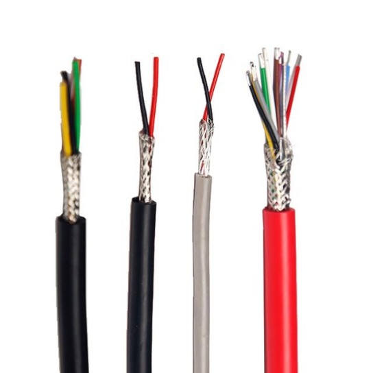
- Braid Shields: Woven mesh of fine metal wires (typically tinned copper).
- Pros: Excellent flexibility, durability, and mechanical strength. Provides good coverage (typically 85%-95%) and effective shielding across a broad frequency range. Good for handling low-frequency interference and handling repeated flexing.
- Cons: Slightly bulkier and heavier than foil shields. Can be more expensive. Coverage isn’t 100%.
- EMI Performance: Very good to excellent, particularly for lower frequencies and demanding physical environments. Often used in flight control, engine sensor wiring, and areas requiring high mechanical resilience. Common styles: Bare Copper, Tinned Copper (enhanced corrosion resistance).
- Foil Shields (Spiral or Longitudinal): Thin metallic foil tape (usually aluminum with a polyester backing for strength), sometimes combined with a drain wire.
- Pros: Lightweight, lower cost, provides 100% coverage against high-frequency capacitive coupling noise. Highly effective at shielding against high-frequency RFI. Space efficient.
- Cons: Less mechanically robust than braid. More susceptible to damage during installation or repeated flexing. Higher resistance at low frequencies compared to braid.
- EMI Performance: Excellent for high-frequency EMI/RFI suppression. Ideal for avionics data busses (ARINC, AFDX), cockpit displays, and sensor lines where static installation or minimal flexing is expected. Drain wire essential for effective grounding.
- Combination (Foil-Braid) Shields: Utilizes both foil and braid layers, often with the braid over the foil.
- Pros: Offers the advantages of both: 100% foil coverage plus the strength, durability, and broad-spectrum shielding of braid. Superior overall shielding effectiveness (SE), especially over very wide frequency ranges.
- Cons: Bulkier, heavier, and most expensive option.
- EMI Performance: The highest level of protection available. Critical for systems operating in extremely noisy environments (near powerful radars, ignition systems) or carrying ultra-sensitive signals. Common in mission-critical avionics, integrated core processors, and sensitive communication links.
Factors Influencing Aviation Cable EMI Shielding Effectiveness (SE)
- Material Conductivity: Higher conductivity (Cu > Al) provides better reflection.
- Material Permeability: Higher permeability (steel, nickel alloys) provides better absorption at lower frequencies (but often at the cost of weight/flexibility).
- Coverage Percentage: The amount of physical overlap in the shield construction (100% for foil).
- Thickness/Weight: Heavier braids or thicker foils generally offer higher SE.
- Integrity: Any damage (nicks, cuts, crushing during installation) dramatically reduces SE. Proper handling is crucial.
- Grounding: Shielding is only as good as its connection to ground. Improper grounding is a primary cause of poor shielding performance.
- Frequency: Different shield types and designs perform better at specific frequency ranges (foil excels at high frequencies, braid at lower/mid).
Testing and Standards for Aviation Cable Shielding
The effectiveness of shielding is rigorously tested using standardized methods:
- MIL-STD-461 (USA): The gold standard for aerospace/defense. Key tests include CS114 (conducted susceptibility, bulk cable injection), RE102 (radiated emissions), and RS103 (radiated susceptibility). Defines pass/fail limits for equipment.
- SAE AS6070/AS6071: Industry standards defining test methods specifically for measuring the Transfer Impedance (
Zt) or Shielding Effectiveness (SE) of individual cables/harnesses. Zt (lower is better) is arguably the most critical intrinsic parameter directly measuring a cable shield’s performance against internal and external interference coupling. SE (measured in dB, higher is better) quantifies the shield’s ability to attenuate radiated fields.
- DO-160 (Section 20 & 21): Environmental test standard for airborne equipment, including susceptibility and emissions testing (conducted and radiated).
- Design Standards: Aircraft manufacturers have specific internal wiring standards (e.g., Airbus ABS 0253, Boeing D6-54487) detailing shield construction requirements (braid density, material, termination methods) for specific applications.
Applications Dictating Shielding Requirements
- High-Reliability Data Busses (AFDX, Mil-STD-1553B): Require high SE to prevent data corruption; often use foil or foil/braid shields.
- Flight Control Systems & Engine Sensors: Demand both high SE and high mechanical resilience; heavily favor robust braid shields.
- Avionics Bays & Cockpit Displays: Concentrated sensitive electronics; shielded cables (often foil or foil/braid) are mandatory to prevent crosstalk and ensure clear instrument readings.
- Communication & Navigation Antenna Feeder Lines: Coaxial cables inherently rely on their outer conductor (braid) as the primary shield to carry signals efficiently and block external interference.
- Electrical Power Feeders: While primarily carrying power, shielded cables prevent the highly noisy high-current switching transients (from actuators, pumps) from radiating and interfering with nearby sensitive systems. Braid shields common.
Choosing the Right Shielded Aviation Cable: FOD Matters
Selecting the correct shield involves balancing EMI requirements, mechanical demands (flexing, abrasion), weight constraints, and cost. Partnering with a supplier deeply experienced in aerospace cable standards is crucial. Key considerations:
- EMI Threat Level: Assess the expected noise environment (near radar? near ignition?).
- Signal Sensitivity: How critical is a noise-free signal?
- Operating Frequency: Match shield type to primary threat frequency.
- Installation Environment: Vibration? Flexing? Space constraints? Potential for damage?
- Regulatory Compliance: Ensure the cable construction meets the necessary specs (MIL spec, OEM internal standard).
- Foreign Object Debris (FOD): Aerospace has zero tolerance for FOD. Cables must not shed braid or foil particles during termination, installation, or service life. Proper shield termination techniques (e.g., crimp shields, conductive backshells, preventing whiskers) are critical FOD prevention measures inherent in quality aviation cabling.
Conclusion: The Essential Guard
The EMI shielding properties of aviation cable are not an optional feature; they are a fundamental engineering requirement for ensuring the safety, reliability, and performance of modern aircraft. From robust copper braids handling flight control signals to sophisticated foil shields protecting high-speed data busses, these barriers safeguard critical signals against the invisible but ever-present threat of electromagnetic interference. Understanding the mechanisms, types, and performance factors of aviation cable shielding is essential for anyone designing, installing, or maintaining aircraft electrical systems. Selecting the right shielded cable for the specific application and adhering to strict termination and installation protocols is paramount in achieving the highest levels of signal integrity and flight safety.


