How to Test Aviation Cable for Noise Interference: A Practical Guide
Noise interference in aviation cable systems is not just an annoyance; it can compromise critical flight data, communication signals, and navigation systems, potentially leading to serious safety hazards. Identifying and mitigating electromagnetic interference (EMI) and radio frequency interference (RFI) is therefore paramount for aircraft safety and reliability. This guide outlines practical methods to effectively test aviation cables for noise interference.
Understanding the Sources of Noise Interference
Before testing, recognize common culprits:
- EMI (Electromagnetic Interference): Generated by onboard electronics (radios, radar, avionics), power lines, motors, generators, and even lightning strikes. It manifests as induced voltages/currents in nearby cables.
- RFI (Radio Frequency Interference): Specific high-frequency noise often from communication transmitters, navigation systems, or external sources like ground radar. It can disrupt sensitive analog signals.
- Ground Loops: Occur when different parts of a system are connected to ground at points with varying electrical potential, causing current flow and noise in signal cables.
- Crosstalk: Unwanted signal coupling between adjacent cables within a harness or conduit.
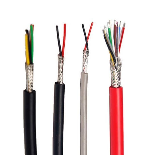
- Poor Shielding/Connections: Damaged cable shields, corroded connectors, or improper termination can drastically increase susceptibility.
Essential Tools for Testing Aviation Cable Noise
Gather these tools:
- Multimeter (Digital): For basic continuity checks, resistance measurements (including shield continuity), and identifying ground loops (measuring voltage between grounds).
- Oscilloscope: The primary tool for visualizing noise. Look for unwanted signals superimposed on the desired signal waveform. Bandwidth should exceed the expected signal frequencies.
- Spectrum Analyzer: Crucial for identifying and characterizing RFI. It displays signal amplitude versus frequency, pinpointing specific interfering frequencies and their strength.
- Signal Generator: Used to inject known test signals into cables for evaluating susceptibility or tracing signal paths.
- Time Domain Reflectometer (TDR): Helps locate cable faults (shorts, opens, impedance mismatches, water ingress) that can act as noise sources or points of susceptibility.
- LCR Meter: Measures inductance (L), capacitance (C), and resistance (R) of cables, which can influence noise coupling.
- Shield Integrity Tester: Specialized tools (like the SIT-1000) designed specifically to test the effectiveness of cable shielding by measuring transfer impedance.
Step-by-Step Testing Procedures
Follow a systematic approach:
- Visual Inspection & Documentation:
- Carefully inspect the cable run, connectors, and termination points. Look for physical damage (kinks, cuts, crushed areas), corrosion, loose connections, or compromised shielding (braid tears, foil damage).
- Verify cable routing. Are signal cables properly separated from high-power cables (AC power, ignition)? Are separation distances maintained per aircraft manuals (e.g., AC 43.13-1B)? Are cables crossing at 90 degrees where necessary?
- Check grounding points for corrosion and secure connections. Ensure shields are grounded at one end only (unless specified otherwise for specific systems like CAN bus), typically at the source end, to prevent ground loops.
- Document findings meticulously.
- Basic Electrical Checks (Multimeter):
- Continuity: Verify conductors are intact (no breaks).
- Shield Continuity: Check the shield is continuous from end to end. Measure resistance between shield and connector shell at both ends (should be very low, e.g., < 1 ohm).
- Insulation Resistance: Measure resistance between conductors and between each conductor and the shield (should be very high, typically > 100 Megohms or as specified). Low resistance indicates potential shorts or moisture ingress.
- Ground Loop Check: Measure DC voltage between the ground points at different ends of the cable/system (should ideally be zero or very low mV). Significant voltage indicates a ground loop potential.
- Dynamic Signal Analysis (Oscilloscope):
- Connect the oscilloscope probe across the signal conductor(s) and the local ground reference at the point of measurement.
- Observe the signal under normal operating conditions. Look for:
- AC Ripple/Hum: Often 50/60Hz or multiples, indicating power supply noise coupling.
- High-Frequency Noise Spikes/Glitches: Could be from switching power supplies, digital circuits, or ignition systems.
- Modulated Noise: Noise that varies with the operation of specific equipment (e.g., noise appears when the radio transmits).
- Compare: Compare the signal at the source end and the load end of the cable. Increased noise at the load end suggests the cable is picking up interference along its path.
- Inject Test Signal (Optional): Use a signal generator to inject a known clean signal at one end. Measure it at the other end with the oscilloscope to see if noise is added during transmission.
- Frequency Domain Analysis (Spectrum Analyzer):
- Connect the spectrum analyzer input across the signal conductor(s) and local ground.
- Scan the relevant frequency range (e.g., from kHz up to several GHz, depending on the system).
- Identify peaks in the spectrum that are not part of the desired signal. Note their frequency and amplitude.
- Correlate: Turn suspected noise sources (radios, radars, specific avionics) on and off. Observe if specific peaks appear or disappear, confirming the source.
- Narrowband vs. Broadband: Identify if the interference is concentrated at specific frequencies (narrowband – likely RFI) or spread across a wide range (broadband – likely EMI from switching noise, sparks).
- Advanced Diagnostics (TDR, LCR Meter, Shield Tester):
- TDR: Connect to the cable. A TDR sends a pulse and analyzes reflections to pinpoint the distance to faults like opens, shorts, crimp issues, or water intrusion that degrade performance and increase noise susceptibility.
- LCR Meter: Measure cable capacitance and inductance. High capacitance can attenuate high-frequency signals, while inductance can affect signal integrity. Compare values to specifications or known good cables.
- Shield Integrity Tester: Follow the tool’s specific procedure. It typically injects a signal between the shield and inner conductor and measures the signal coupled through the shield. A high transfer impedance indicates poor shielding effectiveness.
Interpreting Results and Mitigation Strategies
- Shielding Issues (Poor Continuity, High Transfer Impedance): Repair damaged shield braid/foil. Ensure connectors are properly backshelled and mated. Verify shield grounding (single-point preferred). Consider higher-specification shielded cables.
- Ground Loops: Implement single-point grounding. Use isolation transformers or differential signaling where appropriate. Ensure ground paths are low impedance.
- Crosstalk: Increase separation between noisy and sensitive cables. Use twisted pair cables for differential signals. Route cables perpendicularly where crossings are unavoidable. Consider shielded twisted pairs.
- RFI/EMI Coupling: Improve cable routing/separation. Add ferrite chokes/clamps near connectors on noisy or sensitive lines. Ensure equipment cases are properly bonded. Check filters on power lines entering sensitive equipment.
- Cable Faults (Located by TDR/Insulation Test): Repair or replace damaged cable sections. Address moisture ingress points.
- Noisy Equipment: Ensure equipment meets relevant EMI standards (e.g., DO-160, MIL-STD-461). Add filtering to the noisy equipment’s power or signal lines.
Critical Safety Reminder
Testing on operational aircraft carries inherent risks. Always adhere strictly to aircraft maintenance manuals (AMM), component maintenance manuals (CMM), and standard practices (e.g., AC 43.13-1B). Follow all safety protocols for working on aircraft systems. De-energize systems whenever possible before connecting test equipment. If testing on live systems is unavoidable, exercise extreme caution to prevent shorts, equipment damage, or personal injury. Consult qualified avionics technicians for complex issues.
Conclusion
Effectively testing aviation cables for noise interference requires a methodical approach, combining visual inspection, fundamental electrical checks, and sophisticated signal analysis tools like oscilloscopes and spectrum analyzers. By systematically identifying the type and source of interference – whether EMI, RFI, ground loops, crosstalk, or faulty hardware – maintenance crews and engineers can implement targeted corrective actions. Rigorous adherence to testing procedures and aircraft safety standards is non-negotiable, ensuring the integrity of critical aircraft systems and the safety of flight. Regular inspection and proactive testing are key components of a robust aircraft maintenance program.


