How to Color-Code Aviation Cable Systems: A Clear Guide
Keeping track of countless wires snaking through an aircraft is no small feat. That’s where color-coding comes in – it’s the essential language that ensures safety, simplifies troubleshooting, and speeds up maintenance in aviation cable systems. Getting it right is critical.
Why Color-Coding is Non-Negotiable in Aviation
Imagine trying to fix an electrical issue mid-flight without knowing which wire does what. Color-coding provides instant visual identification of a wire’s function (like power, ground, or signal), its voltage level, and sometimes even its specific circuit. This prevents dangerous mistakes, saves precious time during repairs, and is mandated by strict aviation regulations.
The Standards: AS50881 and MIL-STD-681
While specific aircraft manufacturers might have slight variations, the backbone of aviation wire color-coding comes from two key standards:
- AS50881 (Formerly MIL-W-5088): This is the primary standard used in the United States for wiring aerospace vehicles.
- MIL-STD-681: This standard defines the specific color codes used for wire insulation and the markings applied to wire bundles (harnesses).
Understanding the Two Levels of Coding
Aviation color-coding happens at two distinct levels:
- Individual Wire Insulation Color:
- This color tells you the basic function or voltage level of that single wire.
- It’s applied to the insulation of the wire itself.
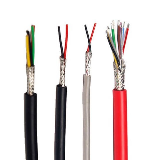
Here’s a breakdown of common wire insulation colors and their meanings:Wire Insulation ColorPrimary MeaningCommon ExamplesBlackGround Circuits (Return Path to Battery Negative)All ground wiresRedDC Power (Battery Positive – Unswitched)Direct battery feed, essential bus feedsYellowAC Power CircuitsWires carrying Alternating Current (e.g., 115V AC)BlueDC Power (Switched or Lower Priority)Feeds from relays, non-essential bus feedsOrangeEssential or Emergency DC PowerFeed from essential bus, emergency bus, invertersGreenAC/DC Equipment GroundingGrounding wires for chassis/safety (distinct from Black)VioletSense Leads, Low Power CircuitsFeedback signals, excitation, low-current controlWhiteNeutral (for AC Power Systems)Return path for AC circuits (paired with Yellow)BrownGenerator Feeds, Variable Speed/FrequencyLeads from generators, constant speed drivesGrayPower Supply Circuits (Often AC Derived DC)Outputs from Transformer Rectifier Units (TRUs)Pink115V AC PowerSpecific identification for high-voltage AC linesTan26V AC PowerSpecific identification for lower-voltage AC linesImportant Note: The exact meaning of a color (especially shades like Blue, Orange, Gray) can sometimes depend on the specific aircraft type and its wiring diagram. Always consult the aircraft’s specific maintenance manual or wiring diagram (WDM) for definitive interpretation.
- Wire Bundle (Harness) Markings:
- These are colored stripes or bands applied to the outer protective sleeve (like convoluted tubing or loom) that bundles multiple wires together.
- They identify the specific bundle and often correspond to a circuit or system group within the aircraft.
- Bundle markings typically consist of a base color and one or more tracer colors (thin stripes of a different color).
- The combination of base + tracer(s) creates a unique identifier for that harness section. For example:
- A bundle might be marked with a Green base and a White tracer.
- Another might have a Red base with Yellow and Blue tracers.
- These codes are defined in the aircraft’s wiring diagram manual. There’s no universal meaning for bundle colors like there is for basic wire insulation; their purpose is unique identification within that specific aircraft.
Best Practices for Aviation Cable Color-Coding
- Consistency is King: Use the same standard (AS50881/MIL-STD-681) throughout the entire aircraft or project. Mixing standards is a recipe for confusion and errors.
- Documentation is Mandatory: Wiring diagrams (WDMs) and maintenance manuals are your bible. They define the exact color codes used for both wires and bundles in that specific aircraft. Never work without them.
- Legibility Matters: Ensure wire insulation colors are vibrant and not faded. Bundle markings must be clear, correctly spaced, and durable enough to withstand the aircraft environment (heat, fluids, abrasion).
- Training is Essential: Anyone working on aircraft wiring must be thoroughly trained on the relevant color-coding standards and how to read the specific aircraft documentation.
- Double-Check: Before making or breaking any connection, verify the wire’s color against the schematic and the bundle marking. A second look can prevent major issues.
- Beware of Variations: Older aircraft or those from different countries might use slightly different schemes. Always verify the applicable standard for the specific aircraft.
- Replace Correctly: When replacing a wire, you must use wire with the correct insulation color code. Don’t substitute colors.
In Summary
Color-coding is the visual language of aviation wiring. Understanding the difference between wire insulation color (indicating function/voltage) and bundle markings (identifying specific harnesses) is fundamental. Always adhere strictly to the relevant standards (AS50881/MIL-STD-681) and, crucially, the specific aircraft’s wiring diagrams. Consistent, accurate color-coding is a cornerstone of aviation safety, reliability, and efficient maintenance. Treat it with the importance it deserves.


