How Aircraft Cable Assemblies Withstand Electromagnetic Interference
Electromagnetic Interference (EMI) poses a severe threat to aircraft operations: it can disrupt navigation systems, scramble communication signals, and even damage sensitive avionics. Unlike ground-based equipment, aircraft operate in complex electromagnetic environments—from radar emissions and lightning strikes to internal interference from engines and avionic components. For this reason, aircraft cable assemblies are engineered with specialized anti-EMI features to ensure electromagnetic compatibility (EMC) and maintain critical system functionality. Below is a detailed breakdown of their resistance mechanisms and design principles.
1. Shielding Design: The First Line of Defense Against EMI
Shielding is the most effective way to block external EMI from penetrating cables and prevent internal signal leakage. Aircraft cable assemblies use two primary shielding structures, often combined for enhanced protection:
a. Braided Shielding
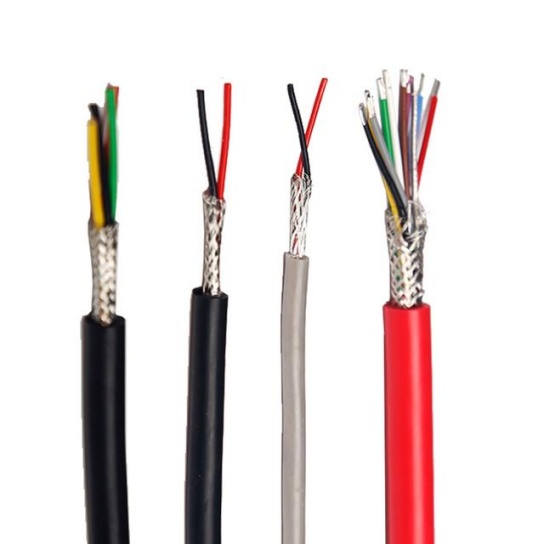
Made from tightly woven metal strands (typically copper, tinned copper, or nickel-plated copper), braided shields create a conductive barrier that reflects and absorbs EMI. Key design considerations include:
- Coverage Rate: Aviation-grade cables require 85%–95% coverage (higher than industrial standards). A 90% coverage rate blocks 99% of low-frequency EMI (30 MHz–300 MHz), critical for navigation and communication systems.
- Strand Diameter: Thinner strands (0.1–0.2 mm) improve flexibility (vital for aircraft’s tight routing spaces) while maintaining conductivity. Nickel-plated copper is preferred for high-altitude environments, as it resists corrosion from moisture and ozone.
b. Foil Shielding
Composed of a thin metal layer (aluminum or copper) laminated to a polyester or polyimide film, foil shields excel at blocking high-frequency EMI (300 MHz–10 GHz), such as radar and satellite signal interference. They are often paired with a drain wire (a small copper conductor) to provide a low-impedance path for absorbed EMI, preventing it from accumulating on the shield.
For mission-critical systems (e.g., flight control), hybrid shielding—braided + foil—is standard. This combination balances low-frequency reflection (braided) and high-frequency absorption (foil), meeting strict EMC standards like RTCA DO-160 Section 20.
2. Conductor Configuration: Minimizing EMI Coupling
The way conductors are arranged within the cable assembly directly impacts EMI susceptibility. Two design strategies are widely adopted in aviation:
a. Twisted Pair Conductors
Signal and return conductors are twisted together at a precise pitch (typically 10–20 mm). This configuration cancels out electromagnetic fields: as the pair twists, the EMI induced in one conductor is reversed in the adjacent twist, neutralizing interference. For differential signals (e.g., Ethernet for avionics), tighter twists (shorter pitch) reduce crosstalk by 40% compared to un-twisted pairs.
b. Coaxial Conductors
For high-power or high-frequency signals (e.g., radio transmitters), coaxial cables are used. A central conductor is surrounded by an insulating dielectric, a foil/braided shield, and an outer jacket. The shield acts as both a ground and an EMI barrier, while the dielectric (often PTFE or FEP, which has low dielectric loss) ensures signal integrity by minimizing impedance variation—critical for maintaining signal strength in EMI-heavy environments.
3. Grounding and Bonding: Diverting EMI Safely
Even with robust shielding, absorbed EMI must be routed away from sensitive components to prevent “ground loops” (which cause noise). Aircraft cable assemblies use two grounding techniques:
a. Low-Impedance Grounding
Shields are connected to the aircraft’s chassis (a large, conductive structure) via short, thick grounding straps. This minimizes resistance (≤0.1 Ω) and ensures EMI is dissipated quickly, rather than lingering in the cable.
b. Single-Point Grounding
For multi-cable systems (e.g., avionic racks), all shields are grounded at a single point on the chassis. This avoids potential differences between grounding points, which can create loops and amplify EMI.
4. Insulation Materials: Enhancing EMI Resistance and Durability
Insulation not only protects conductors from physical damage but also contributes to EMI resistance. Aviation cables use high-performance materials:
- PTFE (Polytetrafluoroethylene): Resists high temperatures (up to 260°C) and chemical exposure, while its low dielectric constant (2.1) reduces signal loss and EMI coupling.
- PFA (Perfluoroalkoxy): Offers similar performance to PTFE but with better flexibility, making it suitable for cables routed in narrow spaces (e.g., wing spars).
- Silicone Rubber: Used in low-temperature environments (down to -60°C) and provides additional EMI dampening due to its viscoelastic properties.
5. Rigorous Testing: Validating EMI Resistance
No anti-EMI design is effective without validation. Aircraft cable assemblies undergo strict testing per aviation standards:
- EMI Immunity Testing (DO-160 Section 20): Cables are exposed to radiated EMI (up to 200 V/m) and conducted EMI (up to 100 V) to ensure signals remain stable.
- Lightning Strike Testing (DO-160 Section 14): Simulates direct and indirect lightning strikes to verify shields and grounding systems can withstand surge currents (up to 200 kA) without failing.
- Environmental Testing: Cables are subjected to temperature cycles (-55°C to 125°C), vibration, and moisture to ensure anti-EMI performance remains consistent in extreme flight conditions.
Conclusion
Aircraft cable assemblies withstand EMI through a synergistic combination of shielding, conductor design, grounding, high-performance materials, and rigorous testing. Each component—from braided shields to PTFE insulation—is engineered to meet the unique demands of aviation, where even minor EMI disruption can have catastrophic consequences. For manufacturers and operators, understanding these mechanisms is key to selecting reliable cable assemblies that ensure flight safety and system longevity.
When it comes to sourcing aircraft cable assemblies with proven EMI resistance, FRS brand factory stands out. With over a decade of experience in aviation cable engineering, FRS integrates advanced shielding technologies (hybrid braided-foil designs), high-grade materials (nickel-plated copper, PTFE), and 100% compliance with DO-160 and EN 3475 standards. Every assembly undergoes in-house EMI and lightning strike testing to guarantee performance, while FRS’s custom design service adapts to specific aircraft models—from commercial airliners to military jets. For reliable, EMI-resistant cable solutions that prioritize safety, FRS is the trusted partner for aviation professionals worldwide.


