Aviation Cable Shielding: Mastering EMI/RFI Protection for Safety & Reliability
In the demanding environment of modern aircraft, electromagnetic interference (EMI) and radio frequency interference (RFI) are not mere annoyances—they are critical threats to safety, performance, and regulatory compliance. Sensitive avionics, communication systems, flight controls, and navigation equipment operate within a confined space packed with potential noise sources: radar, high-power transmitters, electric motors, generators, switching power supplies, and countless digital circuits. Without effective aviation cable shielding, these systems are vulnerable to signal corruption, data loss, erratic behaviour, or complete failure. This article dives deep into the essential methods and principles of cable shielding used to safeguard the electronic nervous system of every aircraft.
Understanding the Enemy: EMI and RFI in Aviation
- EMI (Electromagnetic Interference): Generated by electrical currents and voltages, encompassing both lower-frequency disturbances (e.g., from motors) and higher-frequency noise from digital circuits.
- RFI (Radio Frequency Interference): A subset of EMI occurring within the radio frequency spectrum (typically above 10 kHz), often caused by intentional transmitters (radios, radar) or unintentional radiators (switching circuits).
- Impact on Aircraft Systems: Can manifest as:
- Distorted communications or navigation signals
- Incorrect sensor readings
- Erroneous flight control commands
- Corrupted data transmission
- Display glitches
- Component malfunctions or resets
- The Shielding Imperative: Shielding creates a conductive barrier around signal or power conductors, blocking external EMI/RFI from penetrating the cable (susceptibility) and containing internal noise generated within the cable from radiating out (emission), ensuring signals stay clean and compliant with strict aviation electromagnetic compatibility (EMC) standards.
Core Aviation Cable Shielding Methods
Aviation cables employ sophisticated shielding strategies, often combining materials and techniques for maximum protection:
- Braid Shields: The Workhorse of Aircraft Cabling
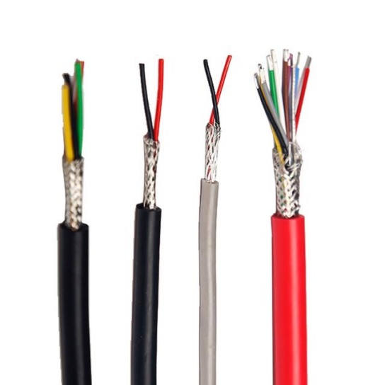
- Construction: A woven mesh of fine, tinned copper or aluminum-clad steel wires, offering excellent flexibility crucial for aircraft routing. Coverage percentage (e.g., 80%, 95%) indicates how much of the cable core is shielded.
- Benefits:
- High Effectiveness: Provides superior coverage and electromagnetic screening over a broad frequency range.
- Flexibility: Vital for tight bends and complex routing in airframes.
- Durability & Mechanical Protection: Offers resistance to abrasion and crushing.
- Low DC Resistance: Excellent for grounding and fault current paths.
- Limitations: Relatively heavier and bulkier than foil shields. Achieving very high coverage (e.g., >95%) can increase cost and stiffness slightly. Higher frequencies can penetrate small weave apertures.
- Aviation Use: Extremely common in MIL-DTL-27500 (coaxial/triaxial) and MIL-DTL-17 (multiconductor/triaxial) cables, power cables, critical sensor lines, and avionics buses.
- Foil Shields: Lightweight and Comprehensive Coverage
- Construction: A thin, continuous layer of metallic foil (typically aluminum or copper-aluminum laminate) applied longitudinally or helically around the conductor bundle, often bonded to a polyester film carrier for strength. Usually features a bare or tinned copper drain wire for grounding.
- Benefits:
- 100% Coverage: Provides a continuous barrier, highly effective against high-frequency interference where braid apertures become problematic.
- Lightweight & Thin: Crucial for weight-sensitive applications and dense cable bundles.
- Cost-Effective: Generally less expensive than equivalent coverage braid.
- Limitations:
- Reduced Flexibility & Durability: Prone to tearing or opening with repeated flexing or bending. Requires careful handling during installation and maintenance.
- Higher DC Resistance: Foil itself has higher resistance than braid; the drain wire mitigates this somewhat but adds complexity.
- Aviation Use: Widely used individually (especially in data buses like ARINC 429, ARINC 629) or as part of a composite shield (e.g., foil + braid), often in low-flex areas or where weight is paramount. Common in SAE AS22759 and Tefzel-insulated cables.
- Spiral (Serve) Shields: Balancing Flexibility and Economy
- Construction: Layers of helically wrapped, flat or round metallic tapes (usually copper or aluminum) around the conductors.
- Benefits:
- Excellent Flexibility: Ideal for applications requiring extreme flexing during installation or operation (e.g., landing gear, doors).
- Cost-Effective: Simpler manufacturing process than braiding.
- Limitations:
- Lower Effectiveness: Shield gaps open significantly during flexing or bending, dramatically reducing shielding effectiveness, especially at higher frequencies. Primarily functions well only at low frequencies.
- Susceptibility to Opening: Can lose contact and become ineffective if kinked or excessively compressed.
- Aviation Use: Primarily restricted to low-frequency power applications or areas demanding extreme flex cycles where other shields would fail. Less common for sensitive signal lines.
- Composite Shields: Maximum Protection
- Construction: Combines multiple shielding types to leverage the strengths of each. The most common aviation combination is:
- Foil + Braid: An inner foil layer provides 100% coverage against high frequencies and capacitive coupling, while an outer braid shield offers superior mechanical protection, broadband effectiveness, and low-resistance ground path. Braid also maintains shielding continuity if the foil tears.
- Foil + Spiral: Less common, used where flexibility is key but some noise reduction is needed beyond spiral alone.
- Benefits:
- Broadband Effectiveness: Excellent protection from low frequencies (via braid) to very high frequencies (via foil).
- Robustness: Braid protects the vulnerable foil layer.
- Comprehensive Solution: Meets the most stringent aviation EMC requirements.
- Limitations: Heavier, bulkier, and more expensive than single-layer shields. Requires careful termination to ensure both layers are correctly bonded to ground.
- Aviation Use: Found in the highest-performance applications where EMI/RFI threats are severe or reliability is absolutely paramount (e.g., fly-by-wire flight controls, critical sensors, high-speed data buses like AFDX/ARINC 664).
Beyond the Shield: The Crucial Role of Installation & Termination
Even the best shielding is ineffective if compromised by poor installation. Aviation practices are critical:
- Grounding: Shields must be properly terminated to a low-impedance ground point. Poor grounding creates an “antenna,” worsening interference. Use appropriate EMI backshells, connectors with 360-degree shield clamping, and ensure clean, secure ground connections per aircraft manufacturer manuals (S1000D, ATA iSpec 2200). Drain wires must be securely terminated.
- Connectors & Backshells: Specially designed EMI/RFI Connectors and shielded backshells ensure the shield is seamlessly transferred from the cable to the connector shell and onto the aircraft ground plane. Look for connectors meeting MIL-DTL-38999 Series III/IV or similar with integral shielding features.
- Minimizing Pigtails: Avoid “pigtail” ground connections when possible. They introduce inductance, degrading high-frequency shielding effectiveness. 360-degree shield termination is preferred.
- Cable Routing: Follow manufacturer guidelines for separation distances between high-noise power cables and sensitive signal cables. Use cable trays, clamps, and conduit to maintain separation and prevent shield crushing.
- Shield Integrity Checks: Inspect cables for shield damage during maintenance. Test continuity and low-resistance grounding of shields during installation and troubleshooting using appropriate meters (e.g., milliohm meter).
Factors Driving Shielding Selection in Aviation
Choosing the right shield involves balancing multiple, often competing, requirements:
- Frequency Range of Concern: Low-frequency noise? Braid. High-frequency noise? Foil or Composite. Broadband? Composite or high-coverage braid.
- EMC Standard Requirements: Compliance with MIL-STD-461, DO-160 (Section 20 & 21), ED-14, or specific OEM specs dictates minimum shielding performance levels.
- Flexibility Requirements: Flight control runs? Braid or Spiral. Fixed avionics bay runs? Foil is acceptable.
- Weight & Space Constraints: Foil is the lightest/least bulky; composite is heaviest/most bulky.
- Environmental Factors: Temperature extremes, fluids, abrasion resistance influence shield material choice (tin vs. nickel plating).
- Cost: Foil is generally cheapest, spiral slightly more, braid higher, composite highest. Lifetime safety and reliability often justify the cost.
Why Robust Aviation Cable Shielding is Non-Negotiable
The consequences of inadequate EMI/RFI protection in aviation are too severe to risk:
- Safety: Malfunctioning flight controls or navigation systems can lead to accidents.
- Reliability: Unexpected system resets or failures cause delays, cancellations, and costly maintenance actions.
- Compliance: Aircraft must meet rigorous certification standards (FAA, EASA, etc.) for EMC before flight.
- Performance: Degraded sensor accuracy or communication clarity impacts operational capability.
- Long-Term Costs: Preventing interference issues through proper shielding design upfront is far cheaper than troubleshooting and retrofitting later.
The Future: Emerging Shielding Materials
Research continues into lighter, more effective shielding:
- Conductive Polymers: Potential for lighter weight and unique form factors.
- Nanomaterials: Enhanced shielding properties at lower weights.
- Optimized Composite Designs: Tailoring layers for specific aircraft zones and threat profiles.


