Aviation Cable in Aircraft Engine Systems: Critical Wiring for Critical Power
Aircraft engines are marvels of engineering, operating under extremes of temperature, vibration, and stress. Reliably delivering power and transmitting critical data within this punishing environment falls, in part, to specialized aviation cable. Understanding its role, construction, and maintenance is vital for ensuring engine performance and safety.
Why Engine System Cables Are Special
Unlike wiring in the cabin or avionics bay, engine wiring faces unique challenges:
- Extreme Temperatures: Close proximity to combustion chambers and exhaust components exposes cables to very high heat. Coolant and airflow can cause rapid temperature cycling.
- Severe Vibration: Engine operation generates intense, constant vibration that can fatigue wires and damage insulation.
- Abrasion & Physical Damage: Cables run through tight spaces, near hot metal edges, moving parts (like actuators), and clamps, risking chafing and cuts.
- Fluid Exposure: Contact with hydraulic fluid, fuel, deicing fluids, and engine oils is common. These fluids can degrade standard insulations.
- Electrical Noise: High-power ignition systems and generators create intense electromagnetic fields, requiring robust shielding for sensitive control signals.
What Makes Aviation Engine Cable Robust?
To withstand these conditions, cables used within aircraft engine systems are built to demanding aerospace specifications:
- High-Temperature Insulation: Materials like PTFE (Teflon™), Tefzel™ (ETFE), or specialized silicone rubbers are used. These maintain flexibility and integrity from very low (-65°C/-85°F) to extremely high temperatures (+200°C/+392°F or higher).
- Superior Abrasion Resistance: Jackets incorporate tough materials like aromatic polyamides (Nomex™) or specialized cross-linked polymers to resist chafing against metal structures and zip ties.
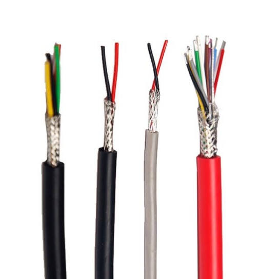
- Advanced Shielding: Multiple layers of braided or spiral-wrapped metallic shielding (often tin-plated copper) protect sensitive signals (like FADEC sensor inputs) from electromagnetic interference (EMI).
- High-Strand Count Conductors: Fine-stranded copper wire bundles allow for flexibility, crucial in vibration-prone areas and routing through confined spaces. Silver-plating enhances conductivity and corrosion resistance at high temps.
- Fluid Resistance: Insulations and jackets are specifically formulated to resist degradation from common aircraft fluids like Skydrol™ hydraulic fluid, jet fuel, and engine oils.
- Fire Resistance: Engine cabling must meet stringent flammability standards (like FAA FAR 25.853 or specific OEM specs) to prevent fire propagation and emit minimal smoke and toxic gases.
Common Applications in the Engine
Aviation cable within engine systems is responsible for:
- Sensor Signals: Transmitting data from temperature probes (EGT, TIT), pressure sensors (oil, fuel), speed sensors (N1, N2), and vibration monitors to the FADEC (Full Authority Digital Engine Control) or EEC (Electronic Engine Control).
- Actuator Control: Carrying control signals to engine actuators (fuel metering valves, variable stator vanes, bleed valves, thrust reversers).
- Ignition System: High-voltage ignition leads to igniter plugs (though these often use specific ignition lead types).
- Starter/Generator: Heavy-gauge cables for high current flow during engine start and generator output.
- Heating Elements: Providing power to anti-ice systems on inlet cowls or probes.
Essential Maintenance & Troubleshooting Guidelines
Reliability is non-negotiable. Key practices include:
- Visual Inspection is Paramount: Regularly inspect cable runs:
- Look for chafing (especially near clamps, brackets, edges).
- Check for crushing, kinks, or sharp bends that can break internal strands.
- Examine for blistered, brittle, cracked, or hard insulation – signs of overheating or chemical attack.
- Look for fluid saturation or swelling of the jacket.
- Inspect connectors for corrosion, bent pins, or signs of arcing.
- Ensure all support clamps and ties are secure and undamaged. Missing or loose clamps lead to vibration damage.
- Adhere to Routing: Ensure cables follow designated paths, maintain correct bend radii (never force them), and are adequately supported and separated from hot surfaces and moving parts. Use the correct clips, sleeves, and grommets.
- Use Correct Replacements: NEVER substitute commercial automotive or generic industrial cable. Use only exact replacement part numbers specified by the aircraft/engine manufacturer or MIL-spec equivalents (like MIL-W-22759, MIL-W-81381, SAE AS22759). Verify temperature rating, wire gauge (AWG), and insulation type. Look for markings on the cable jacket.
- Handle Shielding Properly: During maintenance, ensure shielding integrity is maintained. Grounding connections for shields must be clean and secure to prevent EMI issues.
- Prevent Chafing: Use protective sleeves (splined loom, silicone tape, convoluted tubing) proactively in high-risk areas. Ensure existing sleeving is intact.
- Troubleshoot Intermittents: Issues like flickering gauges or fault codes can often trace back to:
- Damaged/shorted wires near connector backs or clamps.
- Corroded or loose connector pins.
- Broken internal strands causing intermittent opens (especially in vibrating areas). Wiggle tests (gently!) while monitoring signals can help locate these.
- EMI due to compromised shielding.
Conclusion
Aviation cable within aircraft engine systems is far more than just wire. It’s precision-engineered, high-reliability connective tissue operating in an incredibly demanding environment. Understanding its critical nature, robust construction tailored to engine-specific threats, and the paramount importance of meticulous inspection and maintenance practices are fundamental to ensuring the safety, reliability, and performance of the aircraft’s heart. Always prioritize OEM specifications and rigorous procedures when dealing with these vital components.


