Aviation Cable | High-Quality Aerospace Grade Cables
Introduction to High-Performance Aviation Cables
In the demanding world of aerospace engineering, selecting the right aviation cable is critical for ensuring reliable performance, safety, and compliance with stringent industry standards. High-quality aerospace grade cables serve as the nervous system of modern aircraft, transmitting power, data, and control signals across various systems while withstanding extreme environmental conditions.
Aviation cables must meet rigorous specifications including RTCA DO-160 environmental testing, SAE AS standards, and manufacturer-specific requirements from Boeing, Airbus, and other aerospace OEMs. These specialized cables are engineered to perform reliably in temperature extremes from -65°C to +200°C, resist exposure to hydraulic fluids like Skydrol, and maintain signal integrity in high electromagnetic interference (EMI) environments.
Key Aviation Cable Types:
- 50Ω Coaxial Cables for RF and microwave systems
- 75Ω Coaxial Cables for video and audio applications
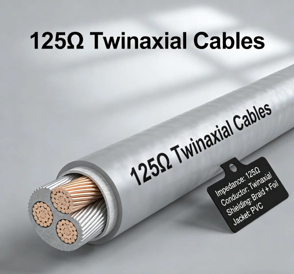
- 125Ω Twinaxial Cables for high-speed data transmission
- High-performance Triaxial Cables for precision instrumentation
- Multi-conductor shielded cables for control systems
50Ω Coaxial Aviation Cables: The RF Backbone
Technical Specifications and Performance
50Ω coaxial cables represent the industry standard for aerospace RF applications, offering optimal balance between power handling capability and signal attenuation. These cables are extensively used in aviation communication systems, GPS navigation, transponders, and radar equipment operating from 0-12 GHz frequency ranges.
Core Construction Features:
- Inner Conductor:Silver-plated copper or copper alloy for superior conductivity
- Dielectric Core:Low-density PTFE or foam PTFE providing consistent 50Ω characteristic impedance
- Shielding:Dual silver-plated copper braids (typically >95% coverage) for excellent EMI protection
- Jacket:Fluorinated polymer outer layer resistant to aviation fluids and abrasion
Critical Performance Parameters:
- VSWR:<1.25:1 across operating frequency range
- Attenuation:As low as 0.30 dB/100m at 10 MHz, scaling appropriately at higher frequencies
- Velocity of Propagation:70-80% typical for PTFE dielectric
- Capacitance:Approximately 30 pF/meter (300 pF/1000 ft)
- Operating Temperature:-65°C to +200°C continuous
Aerospace Applications for 50Ω Coaxial Cables
Communication Systems:
Modern aircraft rely on 50Ω coaxial cables for VHF, UHF, and satellite communication systems. These cables connect transceivers to antennas while maintaining signal integrity and minimizing losses that could compromise communication range and clarity.
Navigation Equipment:
GPS/GNSS receivers, instrument landing systems (ILS), and marker beacon receivers utilize 50Ω coaxial cables to ensure accurate position data transmission with minimal signal degradation.
Surveillance Systems:
Transponders (Mode A/C/S, ADS-B) and TCAS (Traffic Collision Avoidance System) depend on high-quality 50Ω coaxial cables to maintain reliable aircraft identification and collision avoidance capabilities.
Weather Radar:
Onboard weather radar systems operating in X-band frequencies (8-12 GHz) require precision 50Ω coaxial cables with consistent impedance matching to prevent standing waves that could affect radar performance.
125Ω Twinaxial Cables: High-Speed Data Transmission
Design and Construction
125Ω twinaxial cables, also known as twinax, feature two parallel conductors surrounded by a common shield, providing excellent noise rejection for high-speed digital data transmission. These cables are commonly specified for ARINC 429 databus applications and other aviation data bus systems requiring balanced transmission lines.
Structural Components:
- Conductor Pair:Two closely-coupled conductors (typically 22-26 AWG) maintaining precise spacing
- Dielectric:PTFE or FEP insulation maintaining characteristic impedance
- Shield:Overall braided shield (tinned or silver-plated copper)
- Outer Jacket:Flame-retardant, low-smoke materials meeting FAR 25.853 requirements
Performance Advantages:
- Differential Signaling:Rejects common-mode noise through balanced pair geometry
- EMI Immunity:Superior protection against electromagnetic interference from nearby systems
- Data Rates:Supports high-speed serial data up to 100+ Mbps depending on cable length
- Flex Life:Engineered for applications requiring repeated flexing during installation and maintenance
Aviation Applications for 125Ω Twinaxial Cables
ARINC 429 Databus:
The most common application for 125Ω twinaxial cables in commercial aviation is ARINC 429 data bus systems, which connect avionics computers, displays, and sensors in a broadcast communication architecture.
Aircraft Networking:
Modern fly-by-wire systems, integrated modular avionics (IMA), and cabin entertainment systems utilize 125Ω twinaxial cables for reliable high-speed data transmission between Line Replaceable Units (LRUs).
Military Applications:
Tactical data links, fire control systems, and mission-critical avionics in military aircraft often specify 125Ω twinaxial cables for their noise immunity and reliability in harsh electromagnetic environments.
High-Performance Triaxial Cables: Precision Instrumentation
Advanced Triaxial Cable Technology
Triaxial cables represent the pinnacle of aviation cable engineering, featuring three concentric conductors: a central signal conductor, an inner shield (often used as a guard or driven shield), and an outer shield for EMI protection. This sophisticated design provides exceptional noise rejection and signal fidelity for precision measurement and control applications.
Triaxial Cable Architecture:
- Center Conductor:Precision-formed copper conductor for signal transmission
- First Insulation Layer:PTFE dielectric maintaining precise geometry
- Inner Shield:Braided or foil shield (can be driven as guard shield)
- Second Insulation Layer:Additional dielectric layer
- Outer Shield:Heavy braid or combination shield for maximum EMI protection
- Outer Jacket:Abrasion-resistant, fluid-resistant jacket material
Performance Characteristics:
- Characteristic Impedance:Available in 50Ω, 75Ω, and 95Ω variants
- Shielding Effectiveness:>100 dB typical at 100 MHz
- Capacitance:Low capacitance design (typically 60-100 pF/m)
- Attenuation:Optimized for specific frequency ranges
- Flexibility:Engineered for installation in confined spaces
Specialized Aviation Applications
Long Range Navigation (LORAN):
50Ω triaxial cables are specifically designed for LORAN navigation systems, providing enhanced noise rejection compared to standard coaxial cables while maintaining signal integrity over long cable runs.
Automatic Dependent Surveillance (ADS-B):
Next-generation surveillance systems utilizing 1090 MHz Extended Squitter and UAT frequencies benefit from triaxial cable construction’s superior EMI protection, ensuring reliable aircraft position reporting.
Automatic Direction Finding (ADF):
Triaxial cables used in ADF systems provide the noise immunity necessary for detecting weak radio beacon signals in challenging electromagnetic environments.
Flight Test Instrumentation:
High-precision triaxial cables are essential for flight test applications where accurate measurement of sensor signals, strain gauges, and other instrumentation requires maximum noise rejection and signal fidelity.
Electromagnetic Interference Protection: Critical for Aviation Safety
Understanding EMI Challenges in Aviation
Aircraft present one of the most challenging electromagnetic environments imaginable. Aviation cables must operate reliably in proximity to powerful radio transmitters, radar systems, electric motors, switching power supplies, and lightning strikes. Effective EMI protection is not optional—it’s a safety-critical requirement that directly impacts aircraft certification and operational reliability.
Primary EMI Sources in Aircraft:
- Onboard Radiated Emissions:VHF/UHF communication transmitters, radar systems, satellite communication equipment
- Conducted Interference:Switching power supplies, electric motor controllers, inverter systems
- External Threats:Lightning electromagnetic pulses (LEMP), high-intensity radiated fields (HIRF)
- Crosstalk:Interference between adjacent cables in wiring harnesses
Advanced Shielding Technologies
Braided Shielding:
Aviation cables utilize high-coverage braided shields (typically 85-95% minimum) constructed from tinned copper, silver-plated copper, or nickel-plated copper conductors. The tight weave pattern provides excellent low-frequency magnetic field shielding while maintaining flexibility.
Foil Shielding:
Aluminum polyester or aluminum-mylar foil shields provide 100% coverage against high-frequency electric fields. When combined with a drain wire, foil shielding offers cost-effective EMI protection for many aviation applications.
Combination Shielding:
High-performance aviation cables often employ multiple shielding layers—such as foil + braid or dual braids—to provide broadband EMI protection from near-DC to microwave frequencies. This approach is essential for cables carrying sensitive analog signals or high-speed digital data.
Triaxial Design Advantages:
The triple-shield architecture of triaxial cables provides unmatched EMI immunity. The inner shield can be driven as a guard shield, actively canceling interference pickup and providing isolation exceeding 100 dB in many applications.
Compliance with EMI Standards
Aviation cables must demonstrate compliance with rigorous EMI standards including:
RTCA DO-160 Section 20:
- Conducted susceptibility testing (10 kHz – 400 MHz)
- Radiated susceptibility testing (100 MHz – 18 GHz)
- High-Intensity Radiated Field (HIRF) testing up to several thousand volts/meter
EN 3375-001 and EN 2235:
European aerospace standards specifying shielding effectiveness requirements, transfer impedance measurements, and screening attenuation tests for digital data transmission cables.
MIL-DTL-17 and MIL-PRF-39012:
Military specifications governing RF cable performance, including shielding effectiveness, VSWR, and environmental resistance for defense applications.
Laser Marking Technology: Permanent Identification for Aerospace
Advantages of Laser Marking Over Traditional Methods
Laser wire marking has emerged as the preferred identification method for aerospace wiring, offering permanent, high-contrast markings that withstand the harshest aircraft operating conditions. Unlike ink printing or adhesive labels, laser markings become an integral part of the cable jacket, ensuring legibility throughout the aircraft’s service life.
Key Benefits of Laser Marking:
Durability and Permanence:
Laser markings resist fading from UV exposure, abrasion, cleaning solvents, and Skydrol hydraulic fluid. The non-contact marking process creates permanent identification that remains legible even after thousands of flight hours and repeated maintenance cycles.
No Adhesive Failure:
Traditional wire markers and labels can detach due to vibration, temperature cycling, or adhesive degradation. Laser markings eliminate this failure mode entirely, ensuring wire identification remains intact throughout the aircraft lifecycle.
Weight Reduction:
Laser marking eliminates the need for individual wire markers, identification sleeves, and adhesive labels. For a typical commercial aircraft with tens of thousands of wires, this can result in significant weight savings—critical for fuel efficiency and payload capacity.
Regulatory Compliance:
Laser marking meets stringent aerospace standards including Boeing and Airbus specifications. UV laser marking systems are qualified to Airbus standards, providing the fine detail and permanence required for aerospace applications.
Laser Marking Process and Capabilities
UV Laser Technology:
Modern aerospace cable marking utilizes UV laser systems (typically 355 nm wavelength) that provide precise, controlled marking without damaging the underlying cable insulation. UV lasers operate in a “cold marking” mode, preventing thermal damage to sensitive materials.
Marking Speed and Precision:
Advanced laser wire marking machines achieve marking speeds of 35-40 meters per minute while maintaining high precision. Systems can mark wire specifications, part numbers, revision codes, and other critical identification data with excellent readability.
Information Content:
Laser markings can include:
- Wire type and specification (e.g., M27500, M22759)
- Gauge and conductor count
- Voltage rating and temperature rating
- Manufacturer identification and date codes
- Revision levels and certification marks
Quality Assurance:
Automated laser marking systems include vision inspection to verify mark quality and legibility. Statistical process control ensures consistent marking quality across production runs, meeting aerospace quality management requirements.
Standards and Certifications: Ensuring Quality and Reliability
Primary Aerospace Cable Standards
SAE AS Specifications:
- SAE AS22759:Standard for aerospace wire, covering materials, construction, and performance requirements
- SAE AS6070:Specification for lightweight, high-speed data transmission cables
- Material requirements including copper conductor conductivity (>62% IACS) and insulation resistance
Military Specifications:
- MIL-DTL-27500:Space-grade cable specifications requiring nickel-plated copper conductors
- MIL-DTL-17:Coaxial cable performance standards including VSWR and attenuation requirements
- MIL-PRF-39012:RF connector interface and performance standards
European Standards:
- EN 2235:Single and multi-core electrical cables for aerospace applications
- EN 3375-001:Digital data transmission cables
- EN 2267-012:High-temperature arc-resistant cables for aircraft electrical networks
Environmental Testing Requirements
Temperature Extremes:
Aviation cables undergo rigorous thermal cycling between -65°C and +200°C (or higher for engine bay applications), with 50+ cycles required by RTCA DO-160G Section 4. Insulation materials must resist cracking, embrittlement, and degradation throughout this temperature range.
Flame and Smoke Requirements:
All aviation cables must meet FAR 25.853 flammability requirements, demonstrating self-extinguishing characteristics with limited flame spread (≤100 seconds vertical burn test). Additionally, cables must meet Boeing and Airbus toxicity requirements, limiting smoke density and toxic gas emission during combustion.
Fluid Resistance:
Aerospace cables must resist degradation from exposure to Skydrol hydraulic fluid, jet fuel, lubricating oils, and cleaning solvents. Accelerated aging tests verify that cable materials maintain mechanical and electrical properties after fluid exposure.
Mechanical Testing:
- Flex life:Thousands of bend cycles at specified bend radii
- Tensile strength:Verification of conductor and insulation integrity under pull forces
- Abrasion resistance:Surface wear testing to ensure jacket durability
- Crush resistance:Verification that cables maintain performance when subjected to compressive forces
Procurement Considerations for B2B Customers
Technical Specification Review
When sourcing aviation cables for B2B applications, procurement professionals must carefully evaluate technical specifications against application requirements:
Electrical Performance:
- Characteristic impedance matching for RF applications
- Voltage rating appropriate for system requirements (typically 600V for aerospace wire)
- Current-carrying capacity based on conductor size and installation method
- Attenuation characteristics for signal integrity over cable length
Environmental Compatibility:
- Operating temperature range for installation location (cabin, avionics bay, engine nacelle)
- Fluid exposure conditions (Skydrol, fuels, cleaning agents)
- Altitude and pressure considerations for sealed or vented constructions
- Vib ration and flex requirements for moving installations
Regulatory Compliance:
- Certification to applicable standards (SAE, MIL, EN)
- Traceability documentation and material certifications
- Quality management system certifications (AS9100, ISO 9001)
- First Article Inspection (FAI) capabilities for critical applications
Supplier Qualification Criteria
Manufacturing Capabilities:
- In-house extrusion and shielding equipment
- Laser marking capabilities meeting Boeing/Airbus specifications
- Testing laboratories with environmental chambers and electrical test equipment
- Cable assembly capabilities including connector termination and testing
Quality Assurance:
- Statistical process control implementation
- Material traceability from raw materials through finished product
- Regular calibration of test equipment
- Non-conformance management and corrective action processes
Delivery and Support:
- Inventory management for standard aviation cable types
- Custom manufacturing capabilities for specialized requirements
- Technical support for application engineering questions
- Global logistics capabilities for international customers
Installation Best Practices
Cable Routing and Support
Proper installation is critical to realizing the full performance potential of aviation cables:
Separation Requirements:
- Maintain adequate separation between power and signal cables to prevent coupling
- Route sensitive low-level signal cables away from high-power transmitters and switching systems
- Follow aircraft manufacturer wiring separation guidelines (typically specified in wiring diagrams)
Support and Strain Relief:
- Provide adequate support at specified intervals to prevent cable sag and mechanical stress
- Use appropriate clamps and ties that won’t damage cable jackets
- Ensure proper bend radius is maintained (typically 5-10x cable diameter depending on specification)
- Provide strain relief at connector interfaces to prevent conductor fatigue
EMI Mitigation:
- Maintain shield continuity through proper termination at both ends
- Use bulkhead connectors with shield grounding when penetrating metallic barriers
- Implement single-point grounding where appropriate to prevent ground loops
- Consider application of EMI protective sleeving per EN 4674-001 for additional protection
Testing and Verification
Installation Testing:
- Continuity testing of all conductors
- Insulation resistance testing per applicable standards
- Shield integrity verification
- Visual inspection of cable routing and support
- Verification of laser markings remain legible after installation
Future Trends in Aviation Cable Technology
Emerging Technologies
Lightweight Materials:
Ongoing development of lightweight cable constructions utilizing advanced polymers and composite materials can reduce aircraft weight by 25-40% compared to traditional designs, contributing to improved fuel efficiency.
Higher Data Rates:
Next-generation aircraft networking requires cables supporting multi-gigabit data rates. New cable designs optimize characteristic impedance, velocity of propagation, and crosstalk performance for high-speed serial protocols.
Enhanced Environmental Resistance:
Development of cables with extended temperature ranges (-85°C to +260°C) and improved resistance to new-generation hydraulic fluids and deicing compounds.
Smart Cable Technologies:
Integration of condition monitoring capabilities, including distributed temperature sensing and partial discharge detection, enabling predictive maintenance and improved safety.
Professional Summary
Selecting the appropriate aviation cable requires careful consideration of electrical performance, environmental requirements, regulatory compliance, and installation conditions. High-quality aerospace grade cables—whether 50Ω coaxial for RF systems, 125Ω twinaxial for data buses, or high-performance triaxial cables for precision applications—must deliver reliable performance throughout the aircraft lifecycle while meeting stringent safety and EMI protection requirements.
The integration of laser marking technology ensures permanent wire identification that survives the harshest aircraft environments, while advanced shielding techniques provide the electromagnetic compatibility essential for modern avionics systems. For B2B customers in the aerospace industry, partnering with qualified cable manufacturers who understand these complex requirements and maintain appropriate certifications is critical for successful program execution.
As aircraft systems continue evolving toward higher integration, increased data rates, and enhanced safety requirements, the role of high-quality aviation cables becomes even more critical. Investment in properly specified, manufactured, and installed aerospace cables pays dividends through improved reliability, reduced maintenance costs, and enhanced aircraft safety—ultimately contributing to the success of aviation operations worldwide.