Aircraft Cable Assemblies: Resistance to UV Radiation
Aircraft operate in extreme environmental conditions, and one often-overlooked threat to critical systems is ultraviolet (UV) radiation. At high altitudes, the atmosphere provides less protection against UV rays, exposing external and semi-exposed aircraft cable assemblies to intense, prolonged UV exposure. This article explores the effects of UV radiation on aircraft cables, materials and designs that enhance UV resistance, testing standards, and maintenance practices to ensure long-term performance.
1. The Impact of UV Radiation on Aircraft Cable Assemblies
UV radiation—specifically UVA (320–400 nm) and UVB (280–320 nm) wavelengths—causes photo-oxidative degradation of cable materials, compromising both mechanical integrity and electrical performance. Key consequences include:
- Insulation Degradation: Most standard polymer insulations (e.g., unmodified PVC or polyethylene) undergo molecular chain scission when exposed to UV. This leads to brittleness, cracking, or chalking on the insulation surface. Over time, cracks propagate inward, increasing the risk of electrical arcing, short circuits, or moisture ingress—critical failures for avionic systems (e.g., flight control wiring or engine sensors).
- Mechanical Strength Loss: UV exposure weakens the tensile strength and flexibility of cable jackets and insulation. For cables in moving parts (e.g., landing gear or wing flaps), reduced flexibility can cause material fatigue and eventual breakage.
- Color Fading and Thermal Instability: UV radiation breaks down colorants in cable jackets, leading to fading. More importantly, degraded materials lose their ability to withstand temperature fluctuations (a common challenge in aviation), further accelerating wear.
Notably, the risk is amplified for cables in “semi-exposed” areas—such as under cowlings or in cargo holds—where UV penetration is limited but persistent, as degradation occurs gradually and may go undetected during routine inspections.
2. Materials for Enhanced UV Resistance
Selecting the right materials is the first line of defense against UV damage. Aerospace-grade cable assemblies rely on polymers engineered for UV stability, often combined with anti-UV additives. Below are the most effective options:
2.1 Base Polymers
- Fluoropolymers (PTFE, FEP, PFA): These materials are inherently UV-resistant due to their strong carbon-fluorine (C-F) bonds, which resist photo-oxidation. PTFE (polytetrafluoroethylene) is ideal for high-temperature applications (up to 260°C) and is commonly used in engine bay wiring. FEP (fluorinated ethylene propylene) offers better flexibility than PTFE and maintains UV resistance in temperatures up to 200°C, making it suitable for avionic control systems.
- Silicone Rubber: Silicone has good UV resistance but requires modification (e.g., adding titanium dioxide or carbon black) to prevent long-term degradation. Modified silicone is often used in external cables (e.g., antenna wiring) due to its weatherability and flexibility at low temperatures (-60°C to 200°C).
- Polyimide (PI): Polyimide insulations excel in UV resistance and high-temperature tolerance (up to 300°C). They are used in critical systems like radar or satellite communication cables, where reliability in extreme conditions is non-negotiable.
2.2 Anti-UV Additives
Even UV-stable polymers benefit from additives to extend service life:
- UV Absorbers (e.g., benzophenones, triazines): These compounds absorb UV radiation and convert it into harmless heat, preventing it from reaching the polymer’s molecular structure.
- Hindered Amine Light Stabilizers (HALS): HALS act as “radical scavengers,” neutralizing the free radicals generated by UV exposure that cause chain scission. They are particularly effective in polyolefins (e.g., modified polyethylene) used in lightweight cabin wiring.
3. Design Optimizations for UV Protection
Beyond materials, cable assembly design plays a critical role in mitigating UV risk:
- Dual-Layer Insulation: A primary insulation layer (e.g., PTFE) for electrical performance, combined with a secondary UV-resistant jacket (e.g., FEP or modified silicone), creates a barrier against UV penetration. This design is common in external cables exposed to direct sunlight.
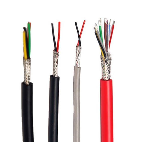
- Shielding Integration: Metal shields (e.g., tinned copper braid) not only protect against electromagnetic interference (EMI) but also act as a physical barrier to UV rays. For semi-exposed cables, a thin aluminum foil shield under the outer jacket enhances UV resistance without adding significant weight.
- Strain Relief and Routing: Proper cable routing (e.g., avoiding direct sunlight on unshielded sections) and strain relief boots (made from UV-stable rubber) reduce stress on cable ends, where insulation is most vulnerable to UV cracking.
4. Testing Standards for UV Resistance in Aerospace Cables
Aerospace cable assemblies must meet rigorous industry standards to ensure UV resistance. Key standards include:
- SAE AS 4074: This standard specifies requirements for insulated electric wires for aerospace applications, including UV resistance testing. The test involves exposing cables to a xenon arc lamp (simulating sunlight) for 1,000 hours, followed by measurements of insulation resistance, tensile strength, and elongation. Cables must retain at least 70% of their original tensile strength to pass.
- FAA AC 20-136: The Federal Aviation Administration (FAA) advisory circular outlines acceptable methods for UV testing of aircraft components. It requires testing under real-world conditions (e.g., temperature cycles between -55°C and 125°C during UV exposure) to simulate high-altitude environments.
- IEC 60068-2-5: The International Electrotechnical Commission (IEC) standard defines UV testing procedures for electrical equipment. For aircraft cables, this includes exposure to UVB radiation (313 nm) at 0.71 W/m² for 500–1,000 hours, with post-test checks for insulation cracking and electrical performance.
5. Maintenance Practices to Preserve UV Resistance
Even UV-resistant cable assemblies require proactive maintenance to extend their service life:
- Regular Visual Inspections: Look for signs of UV damage, such as chalking, cracking, or fading of the outer jacket. Pay special attention to cables near windows, in engine bays, or on wing surfaces—areas with high UV exposure.
- Electrical Testing: Use a megohmmeter to measure insulation resistance annually. A drop in resistance (below 100 MΩ for most aerospace cables) indicates insulation degradation from UV or moisture.
- Replacement of Damaged Cables: If UV damage is detected (e.g., visible cracks), replace the cable assembly immediately. Use only FAA-approved, UV-resistant cables that meet SAE or IEC standards to ensure compatibility and performance.
- Protective Coatings: For older cables or those in high-risk areas, apply a thin layer of aerospace-grade UV protectant (e.g., silicone-based sprays) to reinforce the outer jacket. Ensure the coating is compatible with the cable material to avoid chemical degradation.
Conclusion
UV radiation is a silent threat to aircraft cable assemblies, but its impacts can be mitigated through careful material selection, design optimization, compliance with testing standards, and proactive maintenance. By prioritizing UV resistance in cable procurement and upkeep, airlines and aerospace operators can reduce the risk of critical system failures, extend cable service life, and ensure the safety and reliability of aircraft operations. As aerospace technology advances, new materials (e.g., bio-based polymers with inherent UV stability) and designs will further enhance the resilience of aircraft cable assemblies against extreme environmental conditions.


